 |

|
|
|
|
||
Installing a Radar Detector System in a Gallardo
|
||||||||||||||||||||||||||||||||||||||||||||||||||||||||||||||||||||||||||
|
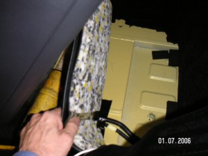
The speaker for the rear detector is placed behind the
drivers seat. The speaker for the front unit is placed under the dash.
For both units the Bel circuit board is removed from its plastic housing
and placed in a watertight plastic box as described in the above Diablo
example.
Again to state the obvious. What I will describe involves opening up and seriously modifying a Bel 980 radar detector unit. You will void the manufactures warranty and can quite easily render the unit useless. If you are not good with your hands, have never done any electrical wiring and soldering, do not attempt this procedure. Get help from a friend.
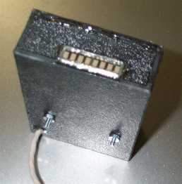
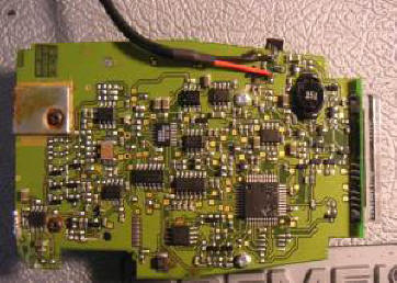
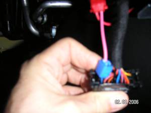
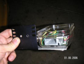
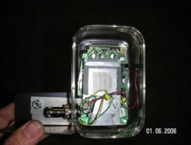
Front Gallardo Radar Detector. The Bel 980 circuit board is first removed from the unit. Bel is continuously upgrading and renumbering their units. You want one that speaks messages. Has auto mode and can be configured to configure itself as it was configured last time before the power was turned off. I set mine to sound level 6. The circuit board must be inserted in a plastic absolutely waterproof box ( Figure 2). I have gone to the extra trouble of de-soldering the Bel 980 LED display and positioning it on to the side of the box so I can see what is happening as well as hearing messages on the speaker. This is a lot of work and should be attempted only by those very experienced in de-soldering/re-soldering. Four wires need to come out of the box. Two for the speaker and the + and - leads. You can use the power socket and jack that comes with the unit or carefully solder the + and - leads directly to the circuit board as shown in figure 3. This is a better arrangement because the plug socket can easily shake loose. In the same way solder two wires where the current two short speaker wires attach to the board. Not seen in figure 3 but on the opposite side, bottom left hand corner. Be real careful not to let the speaker of either of these leads touch any component on the circuit board. (I killed one unit instantly this way!).
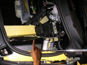
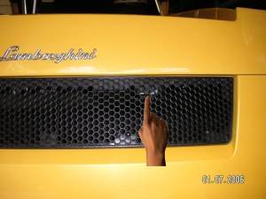
Unlike the Diablo case, we have a great forward location to place the detector unit in a Gallardo. Because the front radiator grill is plastic we can place the unit in the grill air duct and not have any signal loss. Open the four screws that hold the left hand grill in place. Remove the front trunk container unit to expose the other side of the air duct. The radar unit should be held solidly in place by a bracket as shown in figure 4. Two screw holes are drilled into the radiator air duct to hold the radar "box" horizontally as shown in figure 5. One further small hole is drilled to bring the wire leads through the side of radiator air duct. This wire has a rubber grummet through the hole to prevent if from getting frayed over time. The next challenge is to get the power and speaker leads into the interior of the car so you the driver can hear and switch on/off the radar detector.
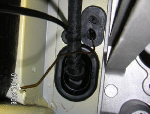
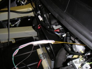
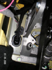
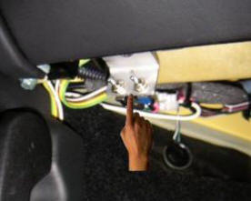
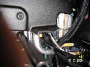
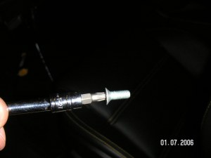
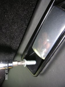
After much searching I found an easy way. It turns out that just above the brake pedal there is a rubber plug that connects the inside of the car with the outside. It is shown in figure 7. To get a wire through it take a piece of strong wire (a straightened coat hanger), and poke it through the rubber plug. It comes out as shown in figure 8. Now attach with tape the radar detector leads to this wire and pull the wire back into the car. This will draw the radar connecting leads through the rubber plug as shown in figure 9.
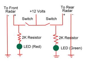
We now need to connect up a switch and LED to let you know the power is on for the unit. Figure 10 is a simple circuit diagram of an arrangement for a front and back units. I like to know each unit is on with a low intensity LED. You can vary the value of the resistor to set the level of brightness you want. They should not be too bright during the day as the can become annoying at night if too bright. Make sure to connect the LED's the right way round otherwise they will not light up. The switches are attached to a small aluminum bracket that I attach under the dash on the left of the steering wheel. I ran the two LEDs down via wires to the side carpet at my feet. You can pick your own location. The speaker (with its 2 wires) is attached to the side of the car under the dash. The Bel unit speaker is fine and is easily heard when driving. Having the ability to switch each unit off and on is nice. Often it is desirable to be able to switch one false alarm source off temporally. The +12 power to the unit comes from a source that goes to 0 volts when the ignition key is turned off. The closest (and easiest source) is the wire going to pin 16 on the OBDII socket. Connect the +12v line is series with an inline 1A fuse to the wire going to this pin. Check you have the +12Volts only with ignition on before connecting the fuse!
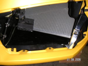
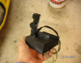
Rear Gallardo Radar Detector. The Bel 980 circuit board is again used here. This time we have to be a little careful where we place the unit in the back of the car because it can get quite hot back there. I found the best location is behind the rear grill over and away from the exhaust radiator box. Again a waterproof box to contain the radar electronics board is essential (fig 13). Recently I found the best boxes are kitchen transparent plastic containers with plastic snap off lids. These are easy to drill and are really water proof. I spray the outside of the unit black when all is assembled. The unit is attached via a "L" shaped bracket to the bar across the top of the rear grill area. The radar detector microwave signal input cone being well below any metal surface and of course facing backwards.
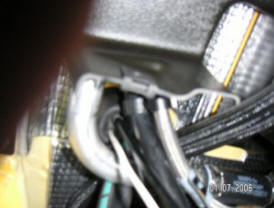
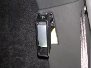
Hooking the wires up to the cars interior is much the same as for the front unit. First one removes the plastic engine area side cover (fig 14). You will need a bar to keep the engine cover up when you remove the left hand side gas piston that normally hold it open. You can run the four wires from the radar detector (2 power lines, and two speaker wires) along the hood release cable all the way to the rear firewall. Use nylon tie downs each few feet. Again Lamborghini has made it easy for us to get the wires into the interior of the car. Where the hood release cable penetrates the firewall is a rubber plug (fig 16,17). This plug is directly behind the hood release lever behind the drivers seat. It's not necessary to remove this lever just open the screw that holds it in place and pull it out (fig 18). As in the case of the front radar detector poke a wire through the rubber plug and pull the wires through. The hardest part of the whole operation is getting the retaining screw that holds the engine hood release lever latch back. The trick is to put a drop of glue on the nut/Allen wrench and use it to hold it in position as you screw it into place (fig 19,20).
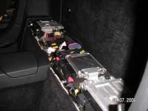
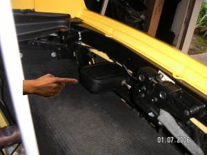
Next you need to run the wires down the back padding on the back wall of the car interior and across the electronics "shelf" behind the seats (fig 21). The cover for this shelf pops up when squeezed in from the door sides. The two speaker wires are connected to the Bel speaker at this point and left sticking out along the back wall. The two power leads then are routed under the seat carpet and up along the side of the car to the switches described above for the front unit. The unit is of course sprayed flat black to merge in with the rest of the components in the engine area of the car (fig 23). All covers etc are returned. Test the unit locally by driving past a known radar source.
|