 |

|
|
|
|
||
Repairing The Carter Motor In A Diablo
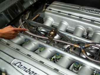
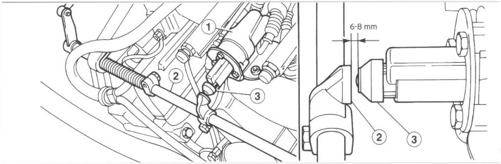
This decreases as time passes, and the accelerator control is released when the engine reaches the correct rpm. If this motor fails, you will get a "L-check engine " light, an OBDII reading "Random Misfire" as well as difficulties keeping the engine turning over at low RPM's when it is cold. Figure 2 (below) shows a diagram of the motor (1) and its position on the engine.
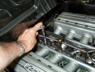
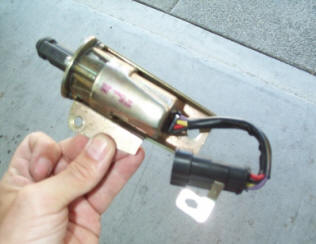
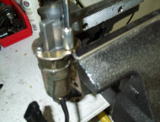
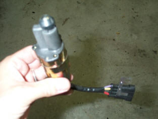
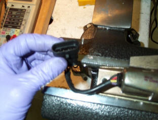
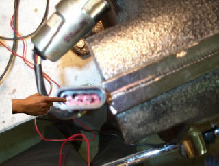
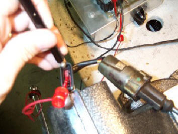
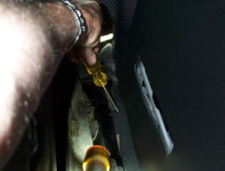
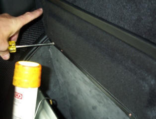
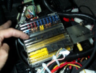
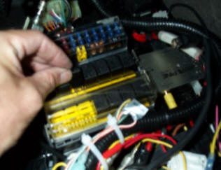
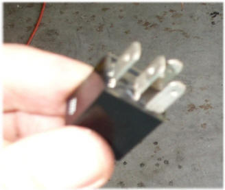
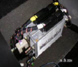
The motor screws in or out the shaft (3) that pushes against the accelerator leaver (2) thereby adjusting the engines air supply. When the engine is cold on startup this shaft is full out opening up air to the engine. When the engine is warm the shaft should wind back and leave a 6-8 mm spacing away from the accelerator bar. The carter motor can fail for a number of reasons. The motor itself could burn out. There is a relay behind the passenger seat that controls the motor could fail or the Carter motor controller itself could fail. Lets look at each in turn. To checkout the carter motor itself we need to remove it from the car. Fortunately this is easy as it is attached by only two bolts (Fig 3). The bracket for the motor can be removed if a replacement is needed (Fig 5) because Lamborghini replacements do not supply the bracket. Figure 7 shows the electrical socket that handles the controls to this motor. It is a 4 pin socket. I will number the pins 1 to 4, with pin 1 indicated in figure 8. Note how the socket is clamped in the vice via the bracket shown in figure 4. Pin 1 is on the opposite side of the bracket. Within the socket pins 3 and 4 have a spacer between them. Now very carefully attach a ground to pin 1 and a +12V wire to pin 2. The motor should briefly start pushing out the connecting rod. It should then stop. Now switch the ground and +12V leads. The connecting rod should pull back in and the motor should then stop. This process can be repeated any number of times. If the motor does not move the rod you have a faulty motor. A second type of carter motor problem is due to a controlling relay that supplies power to the motor. This relay is located in a box behind the drivers seat. Access to the box is simple Pull the drivers seat forward full. Peal back the carpet And open the two screws that hold a panel in place (Fig. 10). You also need to remove two screws that hold the top of the panel in place (Fig. 11). This panel may be just a sheet of Leather covered metal, It may have attached to it a speaker (e.g. In a 1999VT), or it may have attached to it the DVD drive of the navigational system (in my case here). Carefully remove the panel to expose the fuse/relay box area (Fig. 12). On the back of the panel you just removed is a diagram of the fuse and relays and what they are for. Relay #5 is for the carter motor. Count 5 relays down from the back of the car. That is relay #5. remove it and examine it. It should not have any burn marks on it. Unfortunately you cannot see the relay pole contacts so it is not possible to see if it is stuck open or closed. The easiest way to check this relay is to substitute it with relay #11 which controls the air conditioning compressor clutch. Assuming that is working, if you switch the relays and there was a problem with the carter motor relay, once switched the carter motor should now work and the air conditioning compressor should not switch on when it is set to cooler. There are several different relays in this location. They are not all the same so be careful pulling them out. The relays are standard Bosch car relays (Fig. 14). They have numbers on them. If neither of the above tests yield results, then you may have a problem with the "Carter Driver Control Unit" . This is a box that is located beside the LIE computer unit (located behind the passenger seat, Fig 15). This $500 unit is the brain for the Carter motor. It is essentially a small box of diodes and solid state relays that switch on/off the carter motor. While a real electronics expert could de-solder and test the few common components in the unit, for the most of us the best we can do is open the box (four screws one on each corner) and look for any burns on the varnish that covers the components. If you suspect the unit ,you can try the old electronic trick of spraying Freon on the suspected component (Fig 16), and seeing if it affects the carter motor function. If the motor now turns on/off that component may be at fault. The Lamborghini part number for the complete Carter motor control unit is #001637825. Finally if you have a problem with the Carter motor staying on after the engine ignition is switched off -- a serious problem that will run down a battery -- the fault may be with the throttle position sensor (TPS). Please see Adjusting the TPS for more information on this point.
|
 |
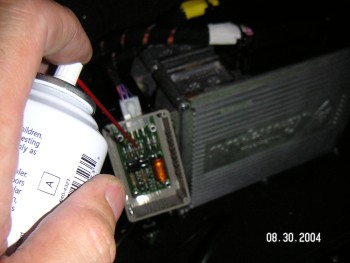 |
| Fig 15. LIE computer and Carter Motor Controller | Fig 16. Freeze components in Carter motor controller |