 |

|
|
|
|
||
Repairing a Broken Side Mirror in a Gallardo
|
|||||||||||||||||||||||||||||||||||||||||||||||||||||||||||||||||||||||||||||||||||||||||||||||||||||||||||||||||||||||||||
|
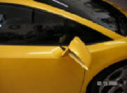
Here is the rub, this agility of this mirror system also makes them somewhat
fragile. The internal swivel mechanism is susceptible to braking.
I broke both of mine in a Shell car wash. Somebody else told me he found
one of his broken after parking the car on a busy street. It was on the
pedestrian side. How can this be?. Is there a repair option?
Well the simplest solution is to simply replace a broken mirror drive
mechanism unit. They run about $900 each just for the mirror housing and
controller.
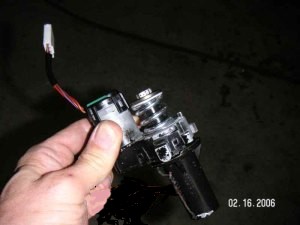
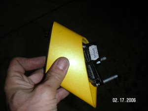
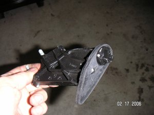
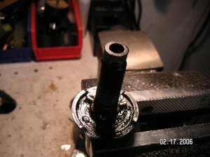
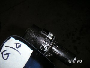
Internals of the Gallardo Side Mirror Controller.
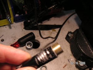
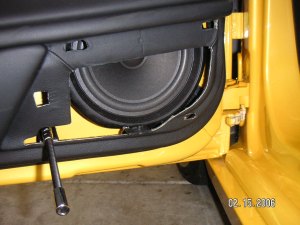
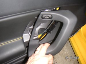
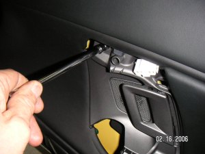
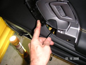
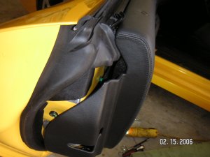
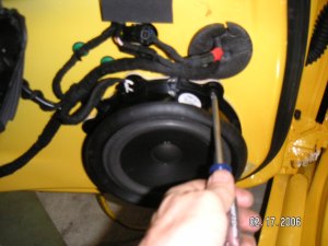
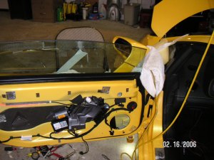
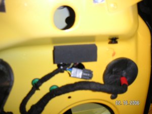
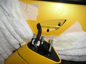
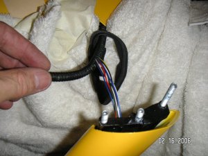
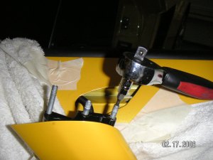
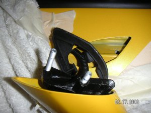
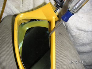
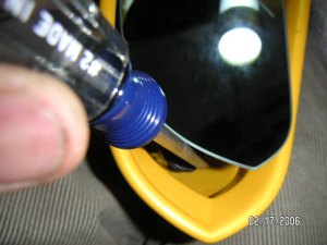
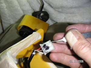
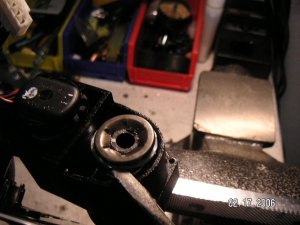
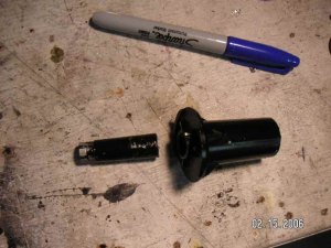
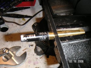
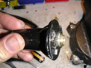
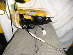
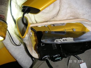
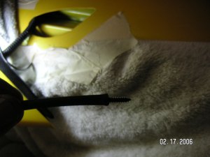
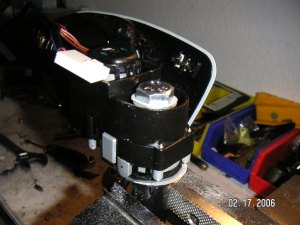
First we need to get the mirror assembly unit open. To do this we must remove it from the car door. This is not as easy as it sounds. The mirror is attached to the car door via 3 bolts that screw into the top section of the door itself. To get at these bolts you must first remove the inside door panel. Remove the speaker grill by removing a nut at the bottom of the grill then pressing the sides inwards slid it forward. This exposed the speaker itself. Remove the door handle by sliding it forward and out (fig 4). Remove the two bolts that are behind the handle (fig 5 & 6). Then carefully go around the edges of the door popping the panel out with a screwdriver or panel removal tool (fig 7). Next remove the speaker (fig 8). Figure 9 shows the door with the speaker removed. Next we need to loosen the wires going to the mirror unit. These wires are shown in figure 10 (the smaller of the two wire bundles). With your hand follow them inside the door up to the mirror. They are bound to the door with nylon ties at places. These need to be cut to loosen up the wire. Now the hard part! The mirror is attached to the top of the door by 3 bolts that have nuts on the inside. These nuts are tight (and are at an angle) and need to be opened. Use a small socket wrench with a long flexible extension. Figure 11 shows the bolts when the mirror is separated from the door. Next we need to draw out some of the connecting wires in the door to give us some room to work on the mirror fig 12. Next we need to remove the outside covering of the extension arm that attaches the mirror to the door. It slides up an internal frame, but to get it completely out you have to remove one of the 3 above mentioned bolts using a thorax socket as shown in figures 13 & 14. You do not need to remove the other two bolts. The cover then slides up exposing the frame that is attached to the actual mirror positioning system. Figures 15 and 16 show the arm support actually removed from the mirror assembly -- this is not necessary in this case. In order to work on the mirror however we need to open the 3 screws at the top of this frame that holds the mirror housing in place. Through the frame are a number of electrical wires (used to position the mirror and heat it). You need to slide the mirror housing along these wires. Fortunately there is wire slack in the door frame. With the mirror housing separated from the mirror arm we now need to get the actual mirror positioning system out of the mirror housing. This mechanism is attached to the mirror housing by 3 screws that take Philips screwdriver to open. If you carefully flip the mirror you can see them (fig 17 & 18). Take real care in doing this so as not to brake the glass in the mirror. Use a small flexible screwdriver. I suspect there is a way to remove the mirror glass by somehow unclipping it, but I have not figured this out. Anybody that has done this please let me know. With the mirror positioning system now free of the mirror housing you can separate the two. However you need to disconnect the controlling wires. There are 3 wires going to one socket the control the positioning system. There is another pair of wires for darkening the glass at night when lights shine on it. There is a further set of wires for heating the mirror glass. All wires are different colors. They disconnect from their sockets easily. The problem is the wires run through the central shaft of the controlling mechanism. In order to completely get the mirror mechanism free we need to remove the wires from their Molex sockets. There is a trick to removing wires from Molex sockets. You stick a fine point needle between the metal and plastic of the socket and pull the lead out (Fig 19). Note the use of tape to protect the paint edges (fig 19)! We can then pull the wires through the small hole in the shaft of the mirror controller. This finally allows you to get the controller out of its housing. An isolated controller is shown in Figure 2. How it works. The mirror assembly rotates on a post through the electrical wires run. There is a gear mechanism which grabs this post and rotates the whole mirror assembly 180 degrees when they are in the parked position. While the mirrors can be rotated by hand this mechanism is not used to position the mirror angle for normal driving. As I said above these posts brake easily. The arrow in Fig 2 points to where the controller post typically brakes. It is made of fragile cast aluminum! Fortunately this material is easy to tread. With a die cut a tread in both sections and with a corresponding brass tubing piece use it to join the broken pieces. (Figure 21-28). The brass tubing I used can be found in any hardware store in the gas/water piping area. Note that gluing the pieces together does not work there is simply too much strain/vibration. Remember it is important to have a hole through the center of the post to tread the mirror controller wires. Attach via tape a wire rod and pull it through the post (fig 29). Then reconstruct the complete mirror assembly (fig 30). One seemly simple task, inserting the 3 retaining screws that holds the mirror mechanism in its housing turned out to be a real challenge. To cut a long story short.. to position each screw insert each screw in a piece or tubing and use it as a flexible support to position it in the appropriate holes. Twist it in, then draw back the tubing. This use a Philips screwdriver to tighten it in place. Done as suggested above and the mirrors function exactly as they did originally and may in fact be stronger!
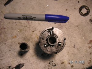
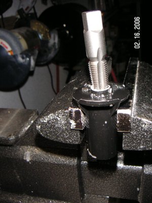
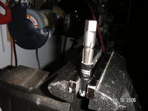
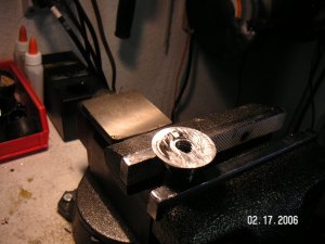
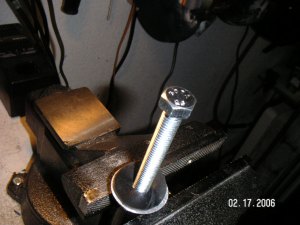
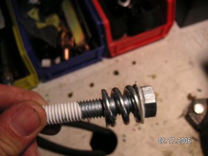
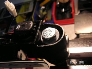
We go about this the same way as described above all the way up to the point where we have the mirror controller out of its casing. At this point instead of rejoining the broken post internally with a brass sleeve; we will replace it entirely with a solid steel bolt. The mirror can be adjusted by hand with this arrangement and is much stronger. As shown below in figure 32 we need to file down the 3 notches that are at the base of the mirror post. We tread the inside to fit the bolt shown in figure 33. Put Teflon tape on the treads insert the spring from the mirror assembly (fig 34) and tighten the post top the assembly so it is with effort adjustable. It is important to have this bolt tight as you do not want your mirror moving around when done. Once the mirror assembly is put back in the mirror housing it will not be possible to tighten the bolt! Figures 36 and 37 show two more views of the assembled mirror mechanism with the post and bolt in place. Reassemble the mirror as described above. You now have one solid mirror!
|
 The
simplest solution would be to simply buy a new mirror post assembly
from Lamborghini. Unfortunately Lamborghini only sells a complete
mirror assembly and mirror housing mechanism as one unit. (BTW, you
can fortunately buy the actual glass mirror and mirror attachment unit
separately). At $900 a unit I looked for an alternative.
Solution 1 is simply a repair approach. The mirror will function as
new but unfortunately will not be any stronger than it was before.
The
simplest solution would be to simply buy a new mirror post assembly
from Lamborghini. Unfortunately Lamborghini only sells a complete
mirror assembly and mirror housing mechanism as one unit. (BTW, you
can fortunately buy the actual glass mirror and mirror attachment unit
separately). At $900 a unit I looked for an alternative.
Solution 1 is simply a repair approach. The mirror will function as
new but unfortunately will not be any stronger than it was before.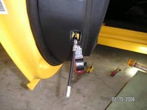
| Final Note. I would like to know if the above mirror swivel mechanism is an OEM part from another Audi car such as an A6. If anybody knows this please let me know as it is often practical to get "used car parts" from these cars. |